Basics
Positive temperature coefficient (PTC) thermistors are devices that act like resistors and increase their resistance because the temperature increases. They will be utilized in cases where a variable resistor is required to manage the flow of electricity flowing through a circuit.
Their use in such a circuits is basically being replaced by metal oxide field effect transistors (MOSFETs). The MOSFET type offers greater power handling capabilities and typically requires a lower voltage drop to attain sufficient current flow than could be needed for an identical PTC device. Nonetheless, PTC thermistors are still often utilized in applications comparable to battery protection circuits because they’re simpler to design in comparison with MOSFETs.
Principle of operation of assorted varieties of PTC thermistors
PTC is a characteristic of PTC brought on by the increased amount of charge carriers present at higher temperatures. The structure and variety of material can have a major impact on the variety of charge carriers. Based on this, we are able to divide them into two categories: polymer PTC thermistor and silicon PTC thermistor.
Polymer PTC thermistor
The fundamental principle that drives a polymer PTC thermistor it is predicated on nature’s resistance to electricity in relation to temperature. This happens since the variety of charge carriers (electrons or sites within the lattice which might be free depending on the materials utilized in semiconductors) that contribute to conduction are activated by heat. In other words, at low temperatures the carriers decelerate and don’t contribute much to the electrical conduction process, but at higher temperatures they move so fast that their contribution increases dramatically. That is shown in Fig. 1 (blue lines) for an imaginary semiconductor material, nevertheless the identical behavior (though in numerous amounts) will be observed with real materials. Polyswitch (blue line), half-fuse and multi-fuse are only a few of the many names utilized in promoting these materials.
Silicone PTC thermistor
Unlike a polymer PTC thermistor which is manufactured from polymer, it’s a silicon PTC thermistor which is well-known for its linear nature, which makes it suitable to be used in the sector of temperature sensing. Normally, the resistivity curve of a silicon PTC thermistor is a straight line (see the blue line in Fig. 1) with a single intersection. This enables the thermistor for use as a temperature sensor. An analog reading proportional to temperature will be specified.
What are PTC thermistors mainly used for?
PTC thermistors are utilized in many applications comparable to:
- Thermal energy management in microprocessors and processors.
- Protection of high voltage power supplies against voltage spikes and overcurrents.
- Ensuring the provision of safety functions for the aviation industry
- As a sensor used to detect static electricity that has built up on the turbine blades of jet engines
- Detection of overheating conditions in electric motors.
- Measurement of the temperature of exhaust gases emitted by combustion engines
PTC thermistors may also be used as: resettable fuse in devices comparable to power supplies, in addition to within the automotive industry.
What’s one of the best option to select one of the best PTC thermistor?
There are various varieties of PTC thermistors, and every has distinct characteristics that make them more suitable for specific applications than others.
- When the protected circuit is working normally, the utmost ambient temperature, the present operating within the circuit, the vital operating time, and other details have to be determined.
- Select various kinds of assembly. For instance, should you are on the lookout for a tool that’s proof against high temperatures and has low energy consumption, a model with an axial cable is one of the best alternative. In case you are on the lookout for a tool with the next current rating or higher temperature sensors, this chip type will be the most suitable option to your requirements.
- Select the product specification that has the biggest “holding current” based on the utmost ambient temperature and circuit operating current.
- Ensure that the operating time of the thermistor you select is lower than the time needed to guard the circuit.
PTC thermistor circuit examples
At normal ambient temperature, the resistance value of the PTC thermistor Rp is lower than the output voltage Rs. When the ambient temperature exceeds this set point, the PTC thermistor resistivity Rp increases rapidly until it reaches Rs as Vo increases.
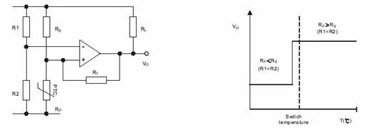
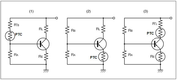
Figure (1) illustrates the fundamental temperature compensation circuit. While you bias a transistor, use a PTC thermistor resistor. If the transistor gets too hot, it’s going to likely cause the PTC thermistor to heat up. When turned on, the PTC thermistor passes through the switching temperature, turns right into a large resistance without affecting the circuit, and turns off the transistor. In the instance shown in figures (2), (3) and (3), it may well even be used as an overheating detector.
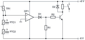
Using multiple PTC thermistors can provide coverage for multiple hot spots if used along with a comparator. The diagram below shows the fundamental circuit which incorporates two PTC thermistor sensors which might be connected to measure the limit temperature after which activate the fan if the limit temperature is exceeded. If the PTC thermistor a minimum of detects an overheating condition, the comparator can operate using the high-temperature resistance. It may be easily replaced with multiple PTC thermistors in addition to induction temperature in the identical circuit.
Application
On this post, we now have discussed the fundamentals of PTC thermistor, its uses, and one of the best option to select the correct one to enhance your work. Unlike NTC thermistorsthey don’t change the input impedance. Due to this fact, they are perfect for circuits that don’t require a change in input impedance. This includes pulse circuits for area amplifiers and measurement equipment.
In case you find an error within the text, please send a message to the writer by choosing the error and pressing Ctrl-Enter.