Entry
The capacitor and resistor suppression circuit consists of: resistor and capacitor connected in series. The resistor is used to soak up the energy of voltage spikes, and the capacitor acts as a brief energy store. In this fashion, the potential of sudden changes in electrical flow damage is reduced.
Why do you wish an RC silencer?
An influence surge occurs when an influence source experiences an intermittent increase in voltage. The issue with current and voltage spikes is that they may cause your electronics to malfunction and fail, even when you don’t notice the issue until it’s too late. This will include a refrigerator, stove, TV, computer and more. These RC suppressors are essential because they supply quick protection against sudden voltage fluctuations. They convert energy into thermal energy reasonably than causing problems akin to electrical surges or melting circuits. These RC attenuators are easy to put in and will be placed on top of your electronics. Moreover, they can assist reduce EMI noise and improve the reliability of the circuit.
(RC attenuator attached to the tip of the cable to “suppress” any current surges)
Principle of operation of the RC suppression circuit
The concept behind the operation of the RC suppression circuit is straightforward. Voltage or current fluctuations are transmitted to a wire connected to an electronic component. there may be a high probability that it will damage the interior circuit. The RC suppression circuit reduces the present and stops any damage.
A relay or SCR controller will be used to alter the resistance provided by this circuit, limiting the flow of electricity through it. Because the voltage increases, the resistance decreases and reverses. Capacitors connected in parallel might be activated when the voltage increases and can give you the option to store additional charge. In turn, the resistance of the resistors decreases and, consequently, the present within the circuit decreases.
Subsequently, an electrical capacitor will be used to limit or absorb voltage spikes. The aim of the resistor is to dissipate or reduce the energy of the magnetic flux on this process to be certain that no harm occurs.
Easy methods to design an RC muffler
First, determine the voltage rating of this switch. It’s important to find out the utmost current rating. needs to be considered together with the minimum resistor rating. Then consider what the switching frequency could be on this particular circuit. Then consider the size capacitor you desire to use on this circuit.
If you’ve determined what frequency to make use of, it is advisable to discover what the RMS voltage is. This is completed by calculation or using charts. After calculating the RMS value, you may determine the quantity of current that may flow through the circuit. Then it is advisable to calculate the duration of the circuit, which is the inverse of the frequency. Then divide this number by the RMS value of the voltage.
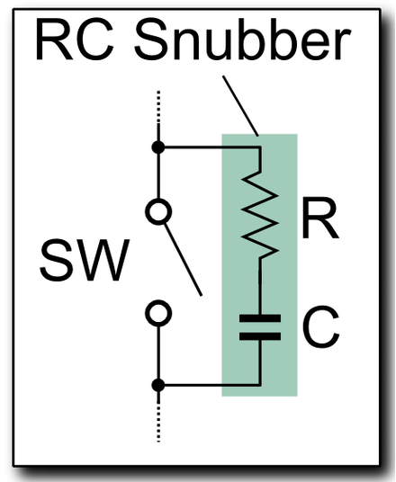
(Typical diagram for one RC silencer)
Resistor selection
One other approach to determining the needed resistance value is to decide on a span. It is a matter of selecting the gap you desire to be from the utmost current output you prefer to to attain when it reaches zero amps. You may then resolve what the minimum amount of current that might be allowed to flow through the system might be. The formula for the resistor value is set by multiplying the intended length by 0.732, which must give a number that, when multiplied by the utmost rated current, equals or exceeds the RMS voltage rating. Once you’ve determined the resistor value that’s most appropriate on your particular circuit, it is suggested to not exceed the limit of this value.
Capacitor selection
You then need to determine on the dimensions of the capacitor needed to offer the suitable amount of current within the circuit. There are three formulas that will be used, but all of them start by determining how much capacitance is required to halve the voltage across the resistance. Once you’ve this information, determine how much ripple voltage might be added to the ultimate value, and then you definitely can select a capacitor that may handle it.
Notes on the usage of RC suppression circuits
1. In accordance with the RC suppressor diagram, the resistance dissipation needs to be identified and handled accordingly to make sure an appropriate heat level. You should utilize this equation to calculate the equation:
Loss=CxVIN2xFSW
Here C stands for capacitance and it’s V In = supply voltage and F SW = switch frequency.
2. If a damping circuit is used, performance might be reduced if the transition from one state to a different is slower. Subsequently, noise levels in addition to energy efficiency have to be taken into consideration.
summary
In brief, an RC suppressor is alleged to be a kind of circuit that’s in a position to absorb voltage spikes and forestall them from damaging equipment or circuits. This inverter example shows an easy RC suppression circuit. It is feasible to configure the damping circuit in various ways to fulfill your requirements.
If you happen to find an error within the text, please send a message to the writer by choosing the error and pressing Ctrl-Enter.